Creating ship models hulls using the method "Shell on thick frames"
Author - Igor Capinos, Poltava , Ukraine (sailmodel.ho.ua )
This presentation discusses a simple, affordable and inexpensive way to build quality basic (roughing) hulls for static shipmodels
Disclaimer
1. All set forth in this presentation are those of the author and do not claim absolute truth.
2. You can apply all the techniques described herein and methods at your own risk. The author assumes no responsibility for use
3. All the materials for this presentation are taken from public sources, mainly from the Internet.
1. On the stability of the ship model's hull.
Stability of ship models hull is the most important criterion of quality. Often modeler sees in winter the hull which was planking in summer appear sufficiently large slit between the planks. Gap may disappear next summer or may be even greater. Because of this modeller has to go to extreme measures - to remove the trim, strengthen body and sheathe again. To prevent such a phenomenon should modeller at the design stage hull design to provide long-term stability.
2 Analysis of today's most popular methods of buildings shipmodel's hulls
1. Wood monolith ( of a single piece of wood ).
2 Set the frame in keel frame .Most known method in the production of the main sets of "models KIT"
Typical hull from modelskit. (Photo from Internet)
3. Plywood frames with filling. The method which has become popular in recent years. The essence of the method is that between frames plywood glued wooden wedges, which are then ground off to obtain the desired shape of the hull.
Hull by R.Yurchenko
4. Package glued blocks. Essence of the method consists in bonding in the package a certain number of sections of the body (more frames) of plywood or wood stove. Method enjoyed by even such famous masters as M.Bezverhny and D.Shevelev.
Hull by M.Bezverkhy
Hull by D.Shevelev
5 "Shell." Professional is rarely used by the method described A.Baranov. The essence of the method in a multilayer planking of wooden slats on wooden boob ( kind of "papier mache" from wood ). For fast fixing brackets used Stapling Gun
Hull by A.Baranov (HMS Cumberland)
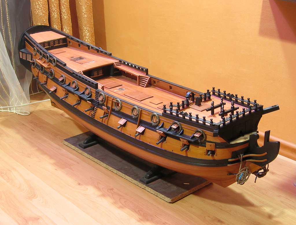
My model of 54-gun ship of the beginning of the XVIII century on the basis of the "shell" by A.Baranov
2.Method "Shell on thick frames"
I specifically explained in detail the method of "shell" although it is rarely used. This method is rarely used because of the high complexity of manufacturing boob. After some consideration I have tried to simplify the process while maintaining its basic dignity. The essence of the method is that boob from a single piece of wood replaced by a set of frames of plywood sufficient (> 10 mm) thickness that allows you use stapler gun.
Step by step description of the process.
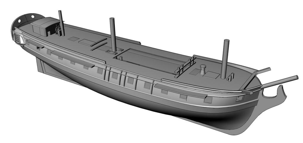
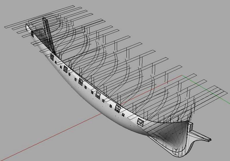
Initial data for the construction of hull is theoretical drawing, but more modern way is creation of 3D models. This model allows you to quickly and accurately obtain any arbitrary cross-section body needed to create a set of frames and other auxiliary elements. The figure shows a 3D-model of the Swedish frigate based on the original drawings of F.Chapman.
Next you need to get cross-section of the hull at the location of technological frames which form the basis of the hull. You need to select material such as 10-mm plywood and draw a suitable cross-section in the location structural frames. Here it is necessary to digress to show the design of the frame and cross-section of the hull.
Midship section
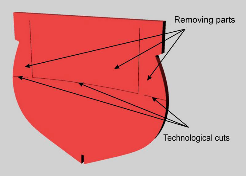
The figure shows a midship section of hull. Frames has parts that are removed after completion of planking (see drawing ). The fault line is usually selected at the level beams of the lower gun deck . In order to get a smooth and clean break, in the frames are made technological cuts. First you break-off middle part then the extreme. Another feature of the frame is a stair in the area of the gunwale that defines the position of the edge plating.
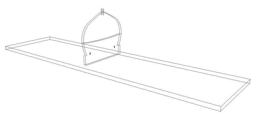
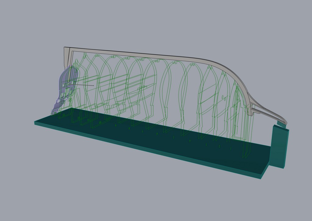
This figure shows the cross section of the model's hull on a building berth. Building berth is a plank suitable size. Each frame is fixed to a pair of building berth self-tapping screws. Such a construction has sufficient rigidity and ensures dimensional stability during planking.
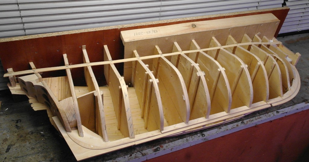
Set
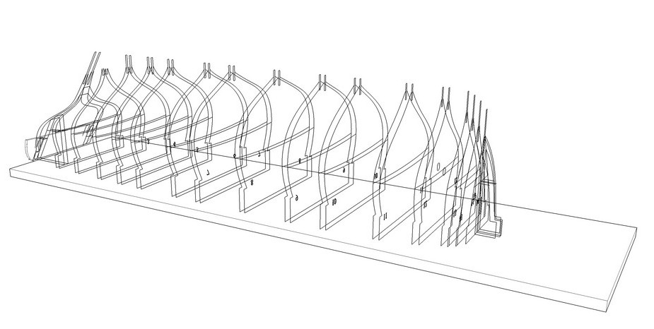
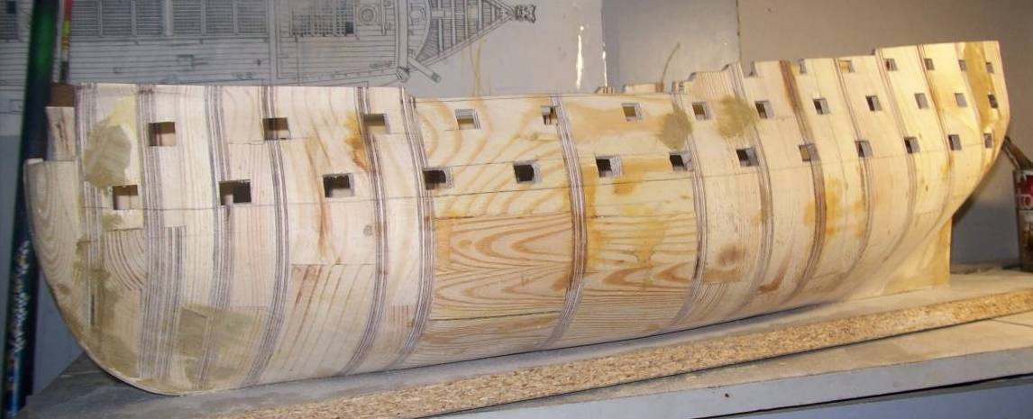
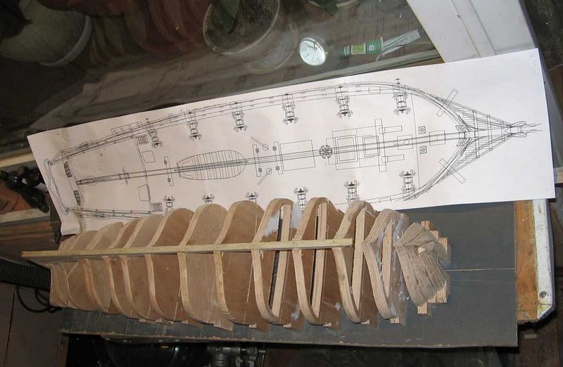
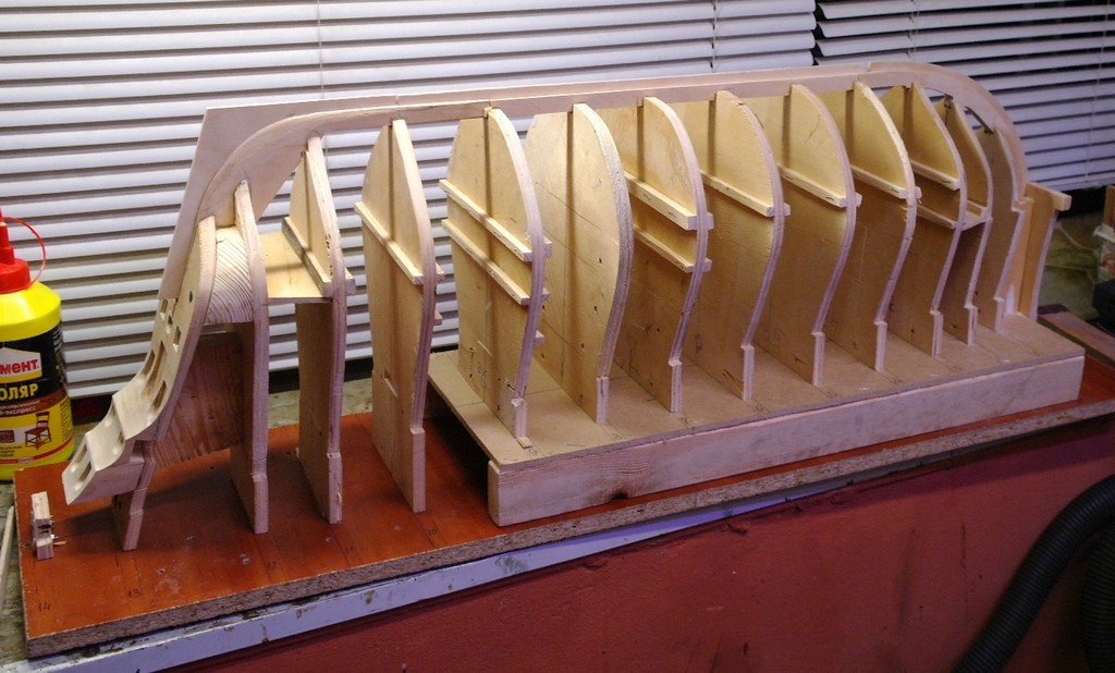
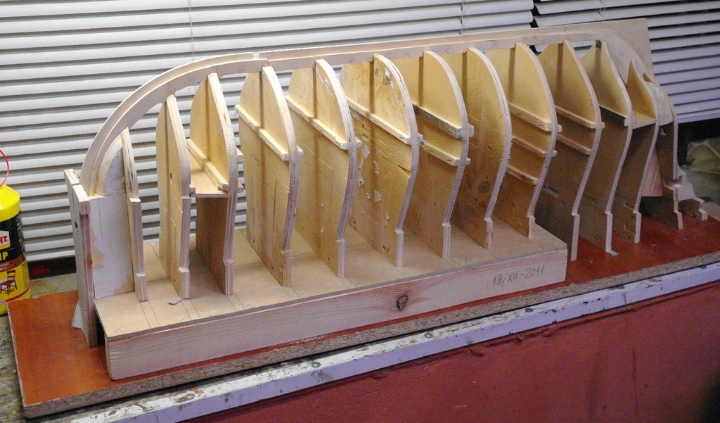
Figure shows a 3D-sketch of the location of structural frames. Frames allocated unevenly along the body, according to the principle "more bending surface - more frames." In the bow are three glued together the frame plus the boss filler in the nose from pine
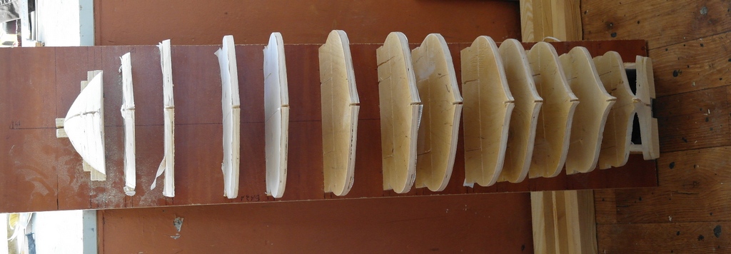
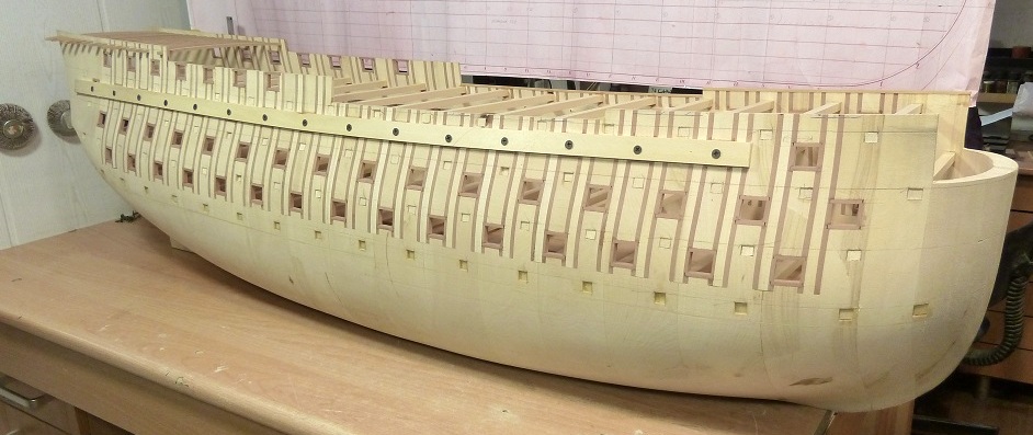
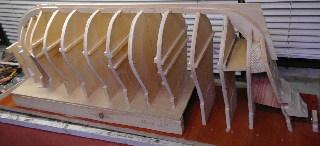
In the photo a set of frames on the building berth ready for plating.
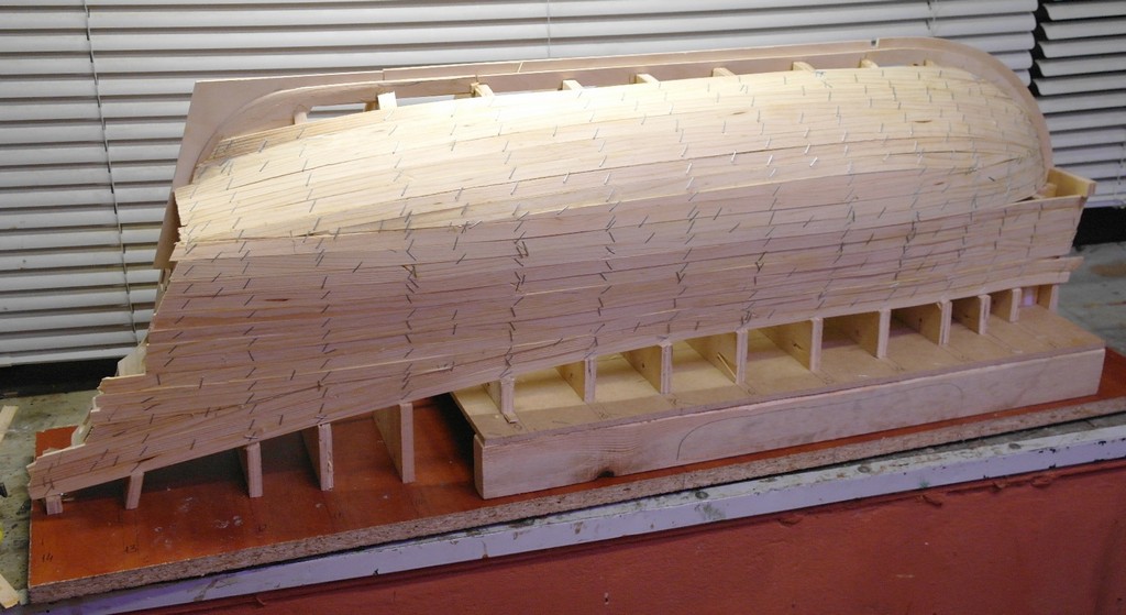
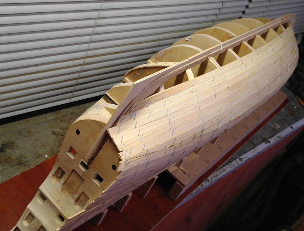
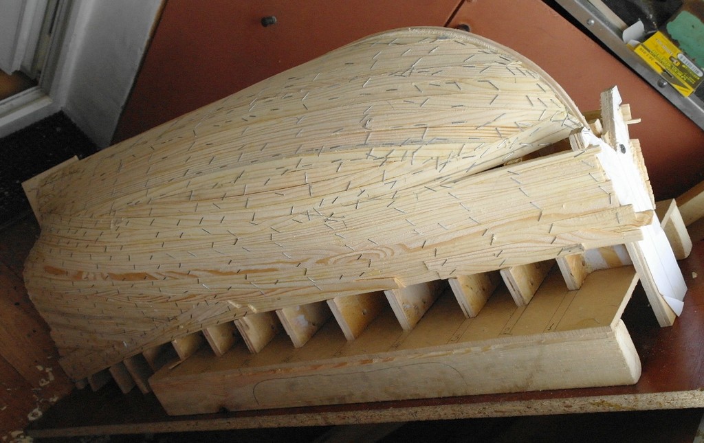
Planking
Planking process is made from pine planks size about 12 X 1.5 mm. You can change the dimensions of planks depending on the dimensions of hull and the curvature of its surfaces. Detachable parts which will not glued to it you must seal with Scotch tape . The process starts from the edge of the gunwale, the first plank rests on intended for this "stair" on a frame.
Plating process step by step:
1.You must choose a plank without knots and other defects. Then you try plank on the place.
2.If you need to bend the plank you dip it in hot water for a few minutes. To facilitate bending you can put on a plank shallow transverse incisions.
3. After you put PVA glue to the ends of the frames and planks is applied and fixed by a stapler gun. Next plank glued in the same manner but glue is applied also on the side end face for gluing to the previous plate.
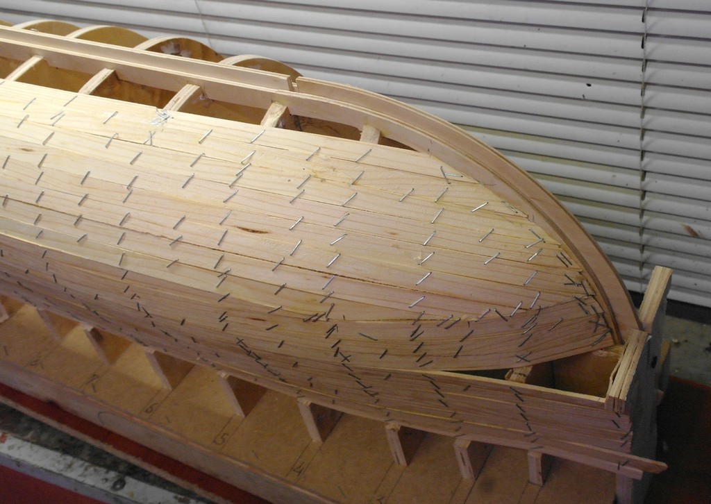
In the process of plating you need to lay planks naturally without much effort. If necessary, you can narrow planks or leave empty seats which you can filled by separate small planks
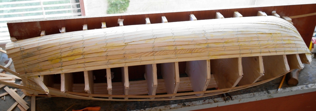
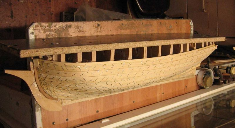
After laying the first layer you need to dry hull at least a day. Then you need to remove staples using a sharpened screwdriver or other tool. Next step to smooth out the surface with the mini-planer and you can lay down a second layer of plating. Planks of the second layer are offset from the planks of the first layer by half the width for a good mix of layers. Even better planks second layer stack is not parallel planks of the first layer but at an angle. This adds great body strength and stiffness.
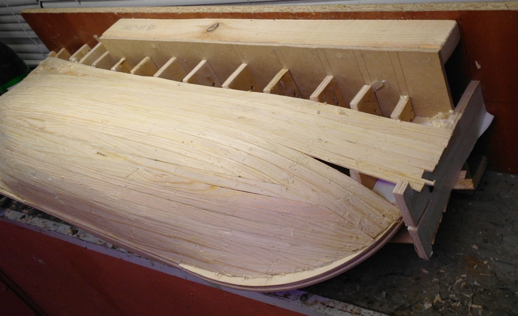
You need to dry second layer about a day and then you must remove the staples and the surface should be smoothind with mini-planer. Next eliminate defects and body puttied, then slotted ports etc. , That is the usual preparing for finishing planking.
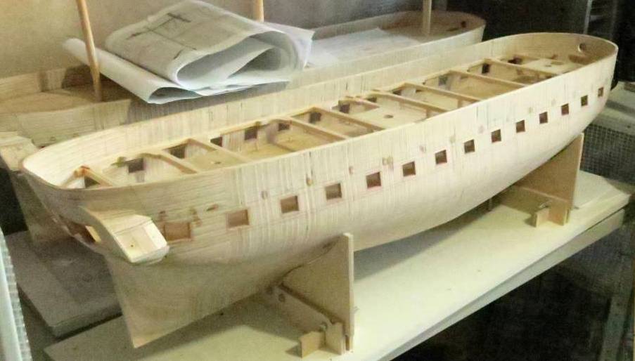
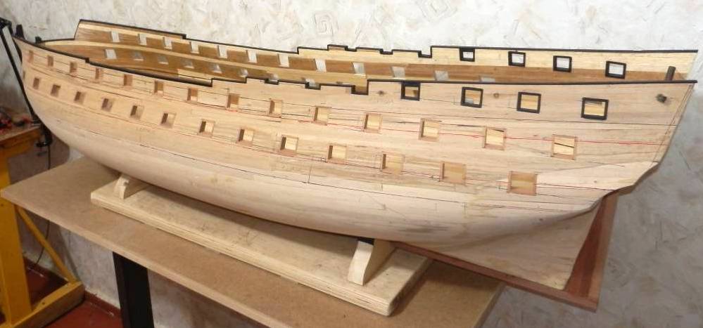
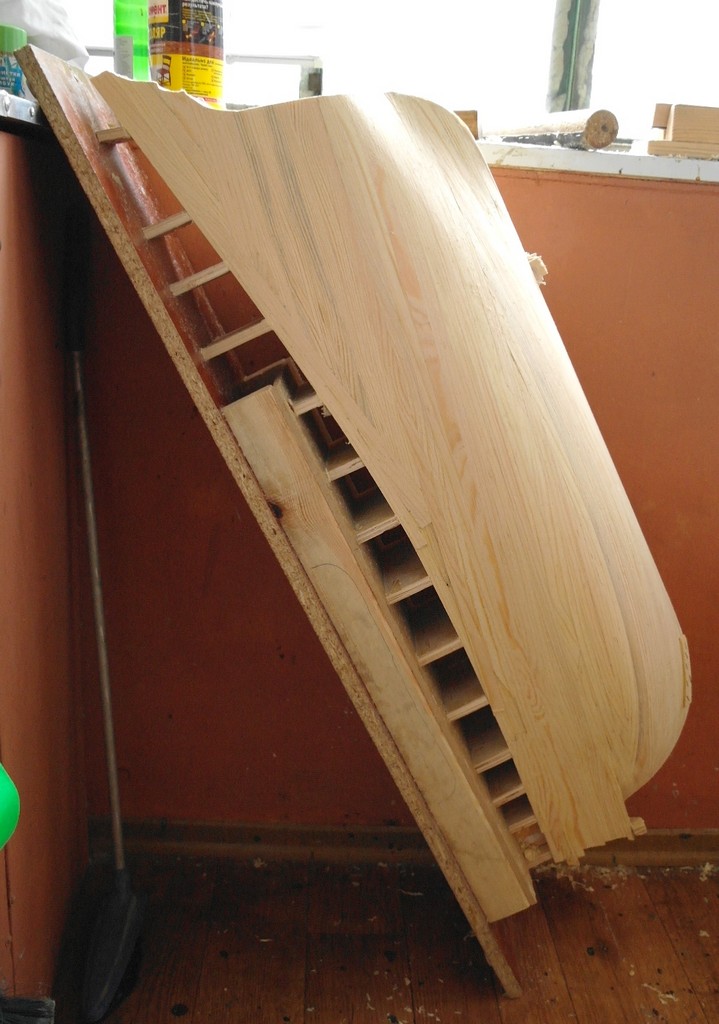
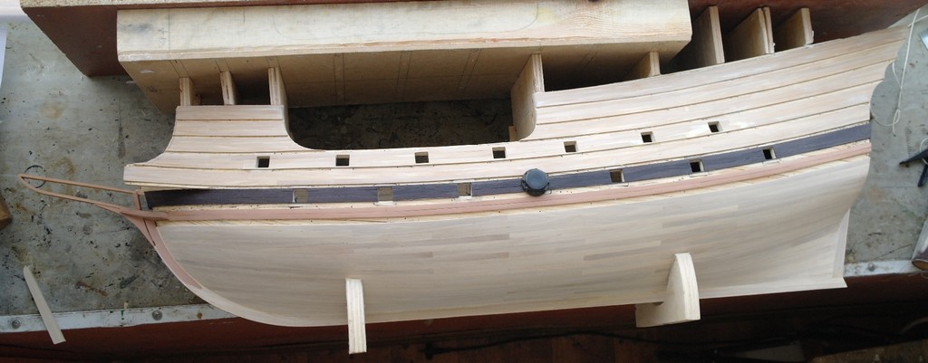
In this photo hull is separated from the building berth and the second layer is treated with a planer.
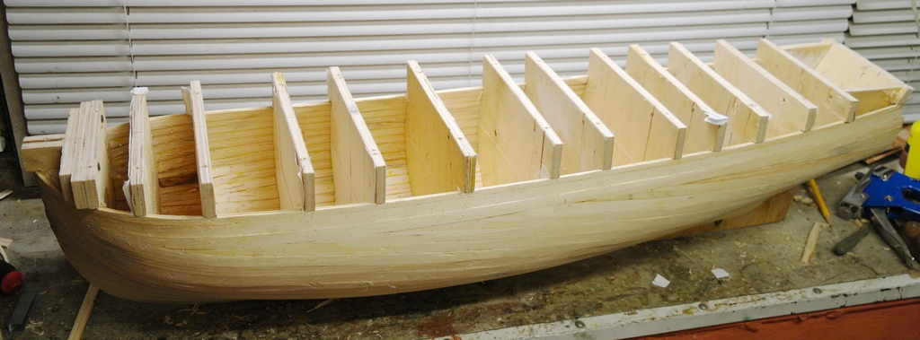
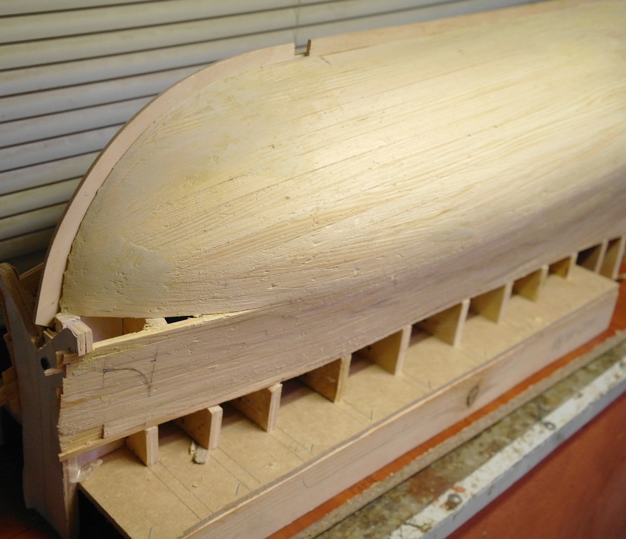
Small video : how to remove breakable parts.
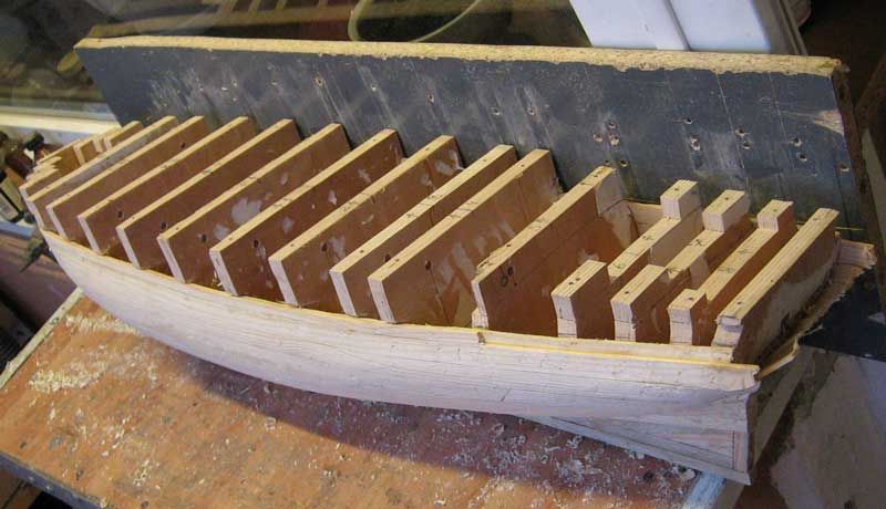
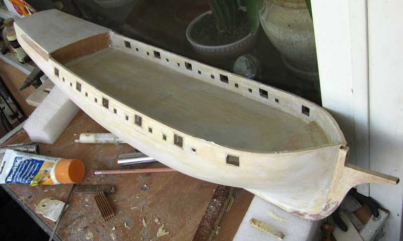
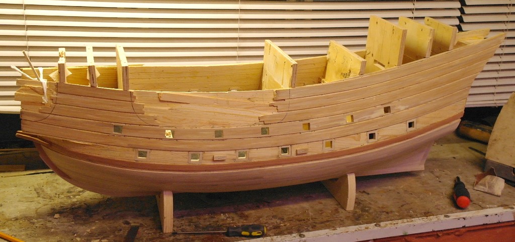
In the photo hull prepared for the finishing planking. Separated parts of the frames were removed and ports were cut
Other examples of hulls made by this technology.
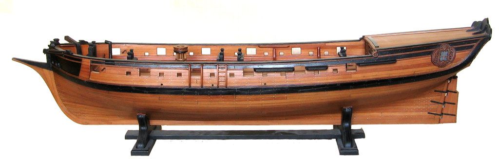
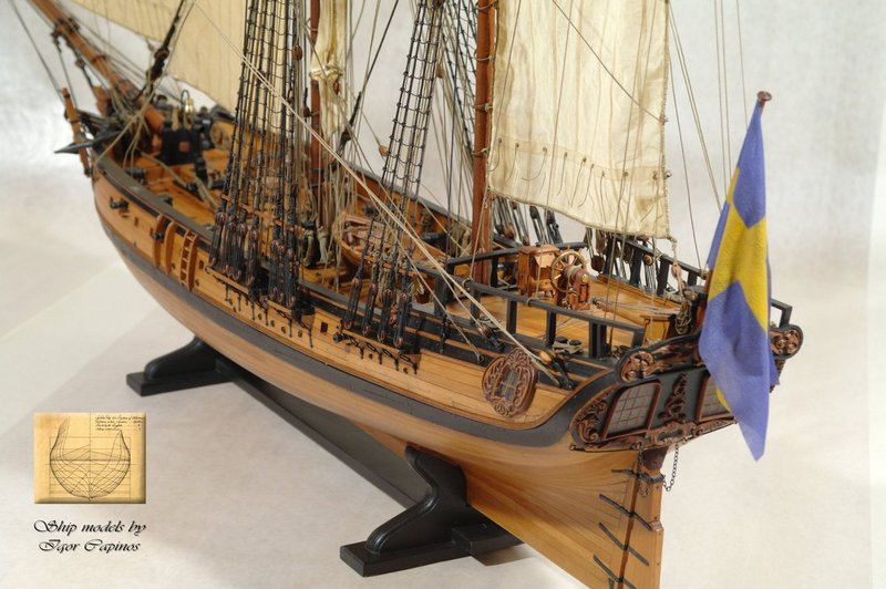
1 Swedish privateer. My first model on which I tried this method. Hull is fairly simple and has no specific features.
.jpg)
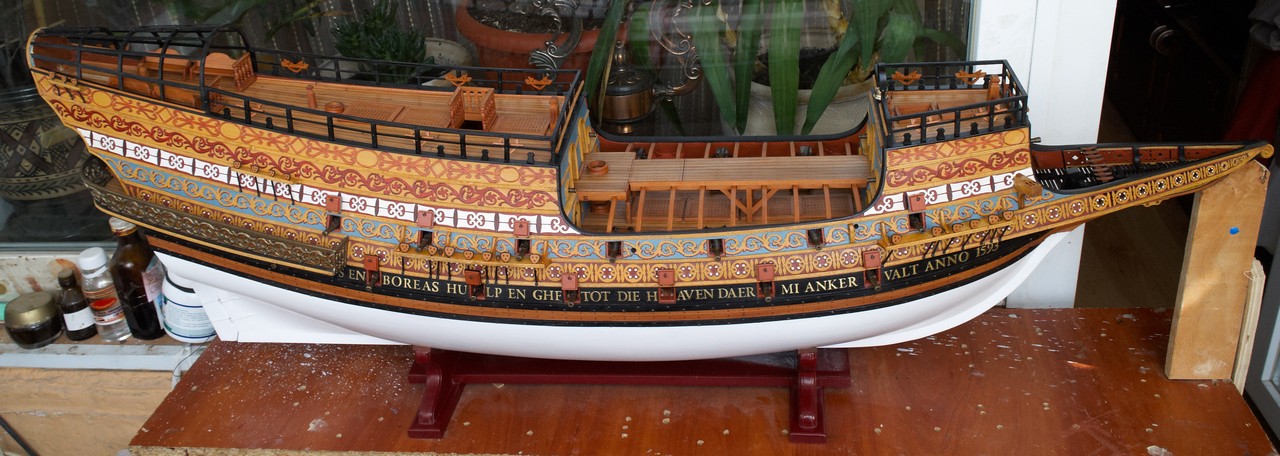
2 Flemish galleon (last project, is published for the first time)
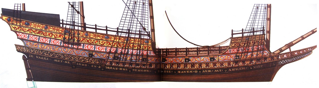
Drawing of Bjorn Landsrom from book "The Ship" is source of reconstruction of model flemish galleon . This drawing is made by model from "El Museo Naval" (Madrid) The model was votive therefore was only a reference point for reconstruction for Bjorn and for me. Everything else is my own vision of what was the galleon. I have used several well-known sources as books Peter Kirsch, "The Galleon: The Great Ship of the Armada Era", Werner Jaeger - Das Peller- Modell von 1603 and contemporary prints and drawings, and so on.).
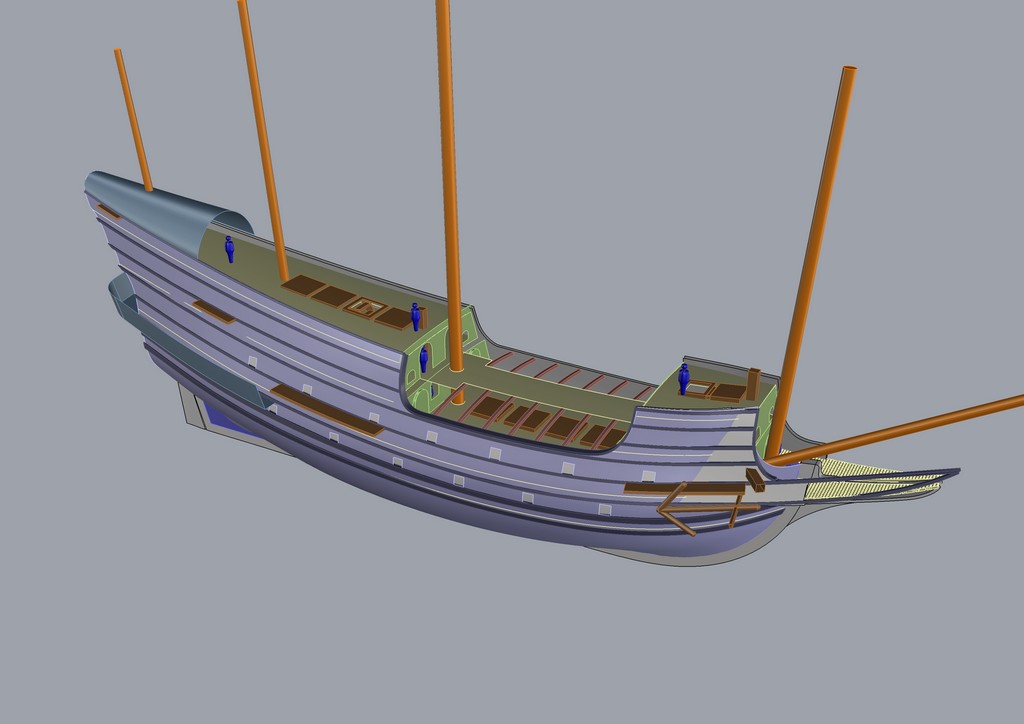
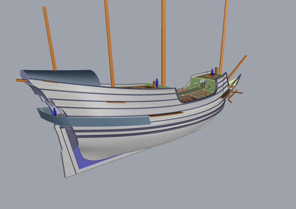
Sketch reconstruction is made in the form of 3D model
s 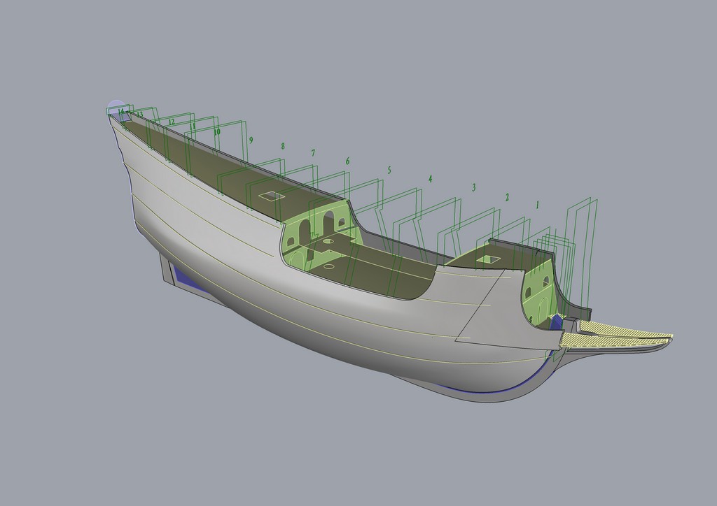
Design of practical frames
Frames set in 3D
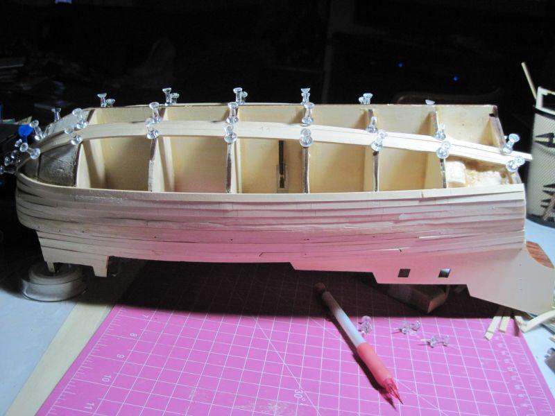
Set in plywood.
Starting planking. 1st layer
On the other hand ...
Before planking 2nd layer
The 2nd layer
2nd layer is fully completed
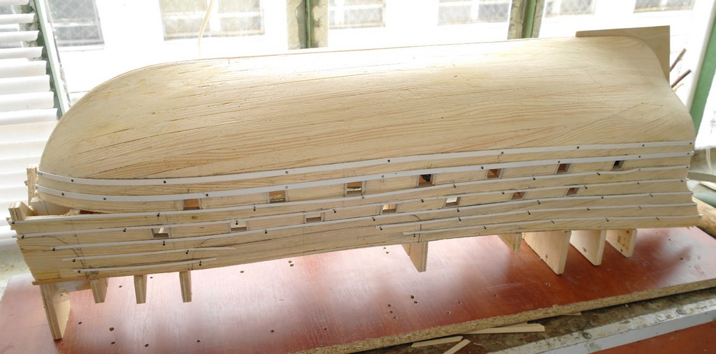
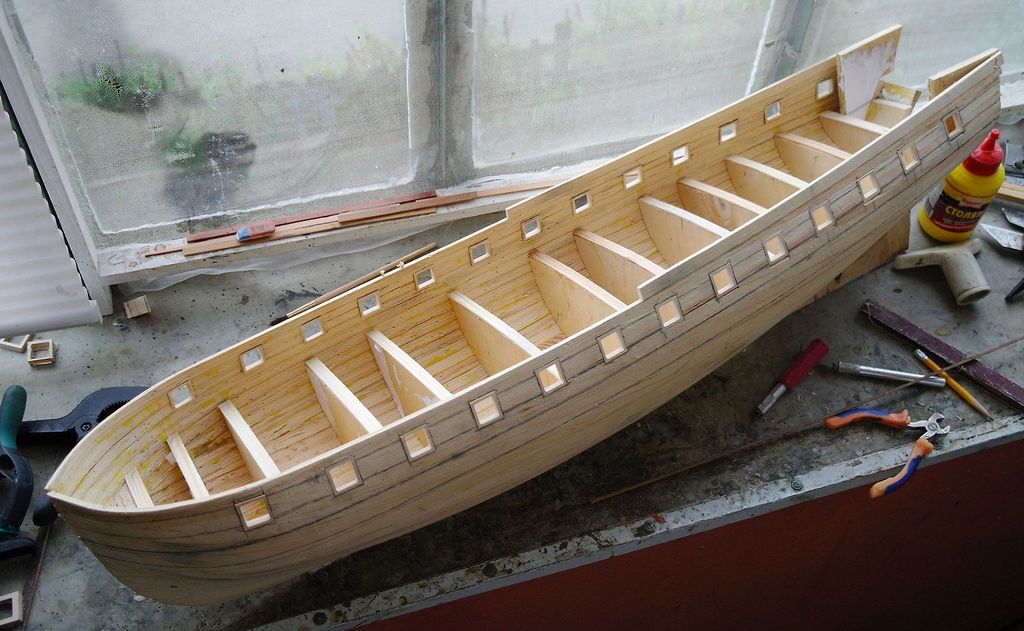
Markup before finishing planking
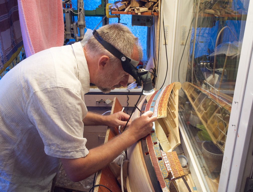
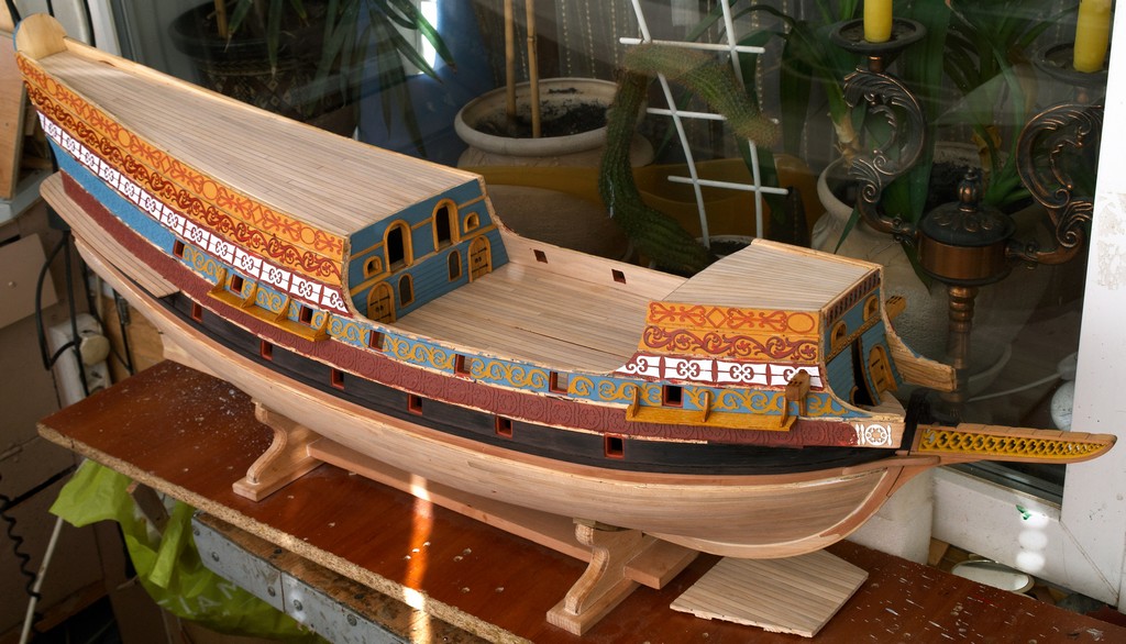
Finishing planking in progress
Finishing planking completed
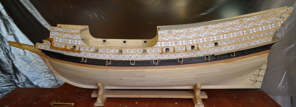
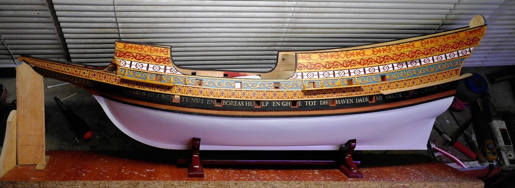
Basis of decor.
Painted decoration.
Continued ...
Hull is ready.
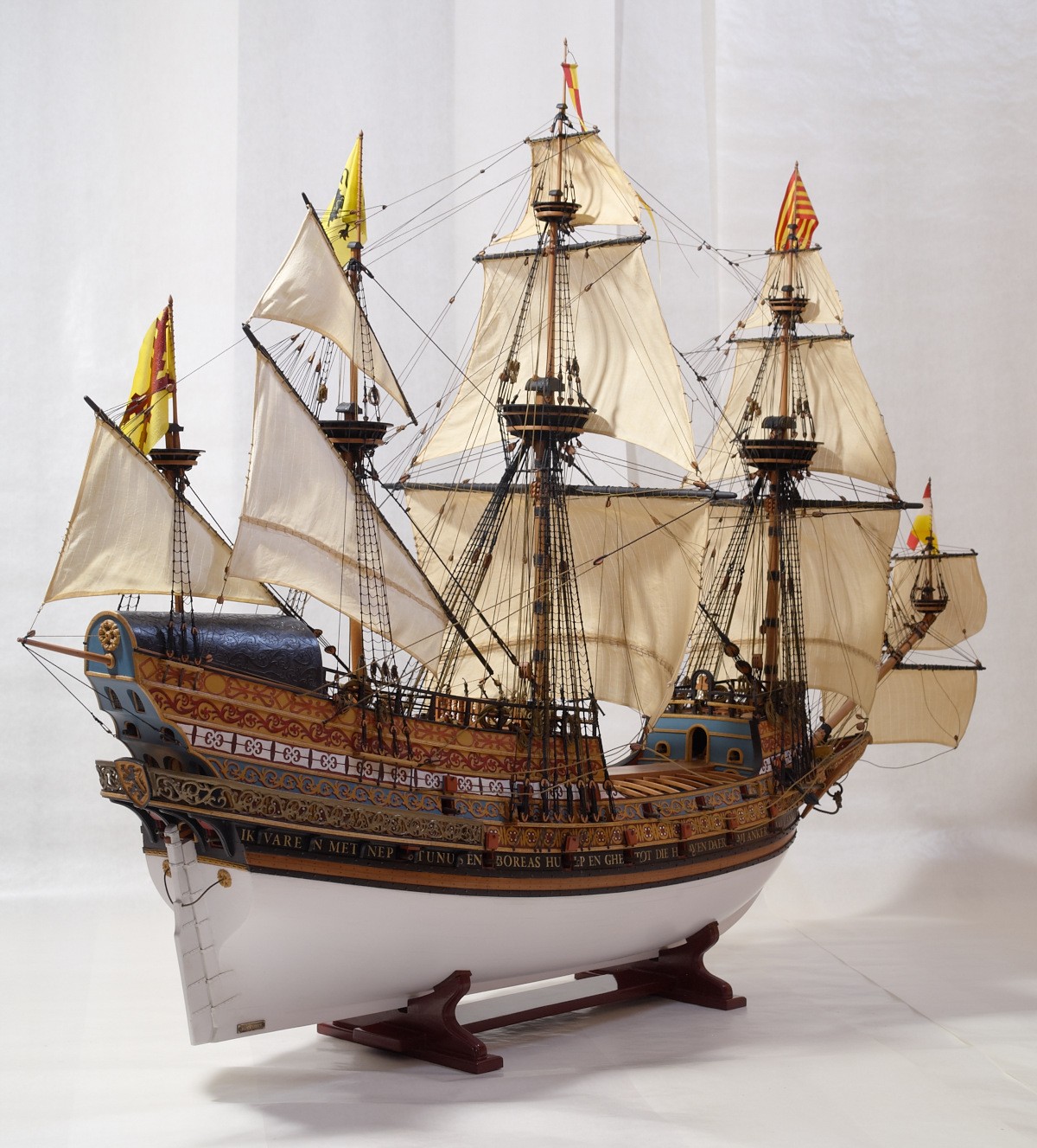
Model is finished
Conclusion
In my presentation I showed one of the available and inexpensive ways to build quality hulls of static shipmodels. I hope this information will be useful to a wide range of modelers. I am pleased to read the comments, corrections and constructive criticism. Write pl031062kia@gmail.com
© 2013-2014 Igor Capinos